I designed the PCB to mount in a frame that I also designed. It was to be milled out of Medium-density fiberboard (MDF). MDF is smooth, easy to cut and shape, and paints well. I have a friend, Denny, who is a retired cabinet maker who agreed to make the frame for my project free of charge! I was going to hire him to make more if I decide to start selling the clocks. That was becoming a real possibility since the clock was generating a lot of interest in those that I showed it to. However, after Denny made the frame for the Senior Project clock, he said he was not interested in making more! I guess it proved more difficult than he had thought. If I do sell clocks, I’ll have to either find someone else to make the frames or figure out how to do it myself.
The board has been assembled
I assembled the board. Whew, that’s a lot of LEDs to solder! I adjusted the code for the test circuit to work on the new clock. However many of the LEDs refused to light!
At first, I thought I had a bad connection on one of the I/O lines, but then discovered what the actual problem was. Early on, I realized that the processor’s RA4 output was not suitable for driving the LEDs. This pin could only sink current, but not source it. The LED matrix required pins that could both source and sink current. Therefore, I had assigned this pin to drive the buzzer. All the buzzer needed was a current sink, so RA4 was dedicated to it. However, somewhere along the way, probably while laying out the PCB, I decided to switch some I/O lines around, and RA4 was connected to the LED matrix instead. So the LEDs that required a current source from RA4 were not lighting!
The parts are here!
I’m so excited that all the parts have arrived! I’m really looking forward to putting it all together!!
PCB layout complete
The PCB layout is complete. Whew that was a lot of work! I’ve ordered the PCB and all the parts to make the clock! Much thanks goes to Bay Area Circuits for their Student Special!
Full schematic is complete
The full schematic for the clock is complete. Now I’m starting the layout of the PCB. This is going to be fun! Nearly 200 components to place, most of them in precise locations. I’m using a spreadsheet to calculate the exact coordinates and angles of the parts. And I’m going to manually route the traces myself. I’m hoping to put all the traces on the back side of the board except the 14 I/O lines for the LEDs will be on the front side in concentric circles among the LEDs.
Test circuit works!
At this point I got the test circuit completely operational and the test software working good. Now it is time to start on the clock itself.
Tested the LED matrix
At this point, I’m able to operate the LEDs of the test circuit by manually applying +5V and ground to the four lines that will be connected to the I/O ports on the microcontroller. I can light any one of the 12 LEDs without having any of the other LEDs light up. This is pretty cool, the technique works!
Received test circuit parts
Received parts. Now it’s time to breadboard the test circuit …
Test circuit parts ordered
Selected components for the test circuit and ordered the parts. I ordered a number of different LEDs in each color and size to see what will work best.
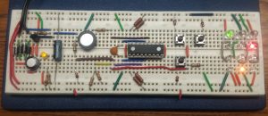
Test schematic
I created a test schematic to run 12 LEDs, the buzzer and three pushbuttons and monitor the 60Hz frequency. The LEDs and pushbuttons will be interfaced with just four I/O lines of the microcontroller This will allow me to test the concepts that will enable me to make the full circuit consisting of 182 LEDs and four pushbuttons interfaced to 14 I/O lines. For both the test and final circuits, the buzzer and 60Hz will each have a dedicated I/O line. Six I/O lines for the test circuit, and 16 I/O lines for the final clock circuit.
You must be logged in to post a comment.