| Proudly featured on the cover of the March 2018 issue of Nuts and Volts magazine! |
I fixed the alarm sound. With the Senior Project clock, the buzzer and the buttons were connected to the same port. On the new clock, they were connected to different ports. I did not update the button reading routine correctly, so the buzzer output was not working at the moment a button was being read. This resulted in a little distortion being introduced into the signal going to the buzzer. This was easily fixed once I figured out what was causing the problem.
However, I made a discovery while troubleshooting this problem. While looking at the buzzer’s waveform on an oscilloscope, I saw voltage spikes being generated by the buzzer’s coil. I realized that I needed to add a diode to the circuit to protect the microcontroller from these spikes.
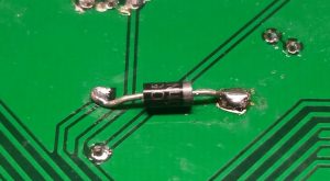
I was surprised to see the spikes as the microcontroller has built in protection diodes on its outputs. I consulted the datasheet and discovered that it has these diodes on all the outputs, except the RA4 output that was being used to drive the buzzer. The RA4 output is not suitable for driving the LEDs, so I’m stuck with using it for the buzzer and therefore need to add the diode. After adding the diode to the back of the board, I looked at the waveform again and the spikes were gone!
You must be logged in to post a comment.